THE 2017 EXCELLENCE IN STRUCTURAL
ENGINEERING AWARDS GALA
|
|
|
|
|
|
|
|
|
|
|
|
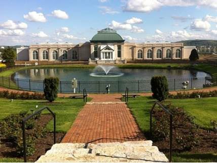
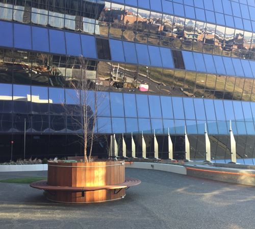
Milton & Catherine Hershey Conservatory at Hershey Gardens
Hershey, Pennsylvania
Keast & Hood
New Construction Under $25M - Outstanding Project Award
From the Judges: The committee appreciated the design team’s commitment to preserving the architectural design while finding creative engineering solutions to the wind-tunnel-identified lateral displacements and accelerations, including the “virtual outrigger” system.
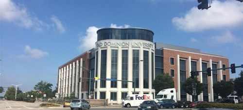
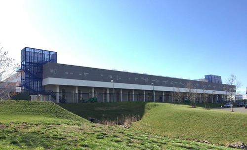
Old Dominion University, Darden College of Education
Norfolk, Virginia
Keast & Hood
New Construction $25M-$75M - Merit Award
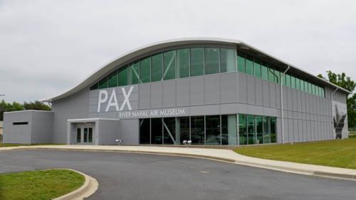
Patuxent River Naval Air Museum and Visitors Center
Lexington Park, Maryland
Woods Peacock Engineering Consultants, Inc.
New Construction Under $25M - Outstanding Project Award
From the Judges: The committee was particularly impressed with the long-span, curved steel trusses which were coordinated with other disciplines to create a structurally sound yet aesthetically pleasing result. The additional complications of a contractor change mid-construction was handled cleanly and without negative impact to the project.
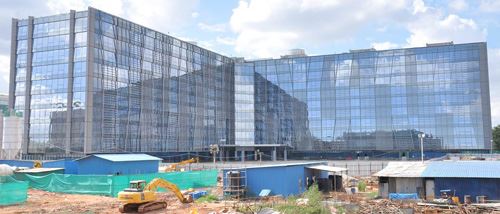
Bangalore Office Building
Bangalore, India
Thornton Tomasetti Group, Inc.
Specialized - Merit Award
From the outside, the 650,000 SF Bangalore Office Building looks like a typical 10-story, curtain-wall-clad building. However, the structural system within represents an innovative engineering endeavor. The building is a top-down structure; all ten of its steel-framed floors were fully assembled on the ground, then lifted and locked into place. This system enabled a bold architectural vision that called for the building’s entire perimeter to be column-free. It also allowed a streamlined construction process in which a majority of various trades could work faster, easier, and safer. Seven concrete cores comprising the building’s gravity and lateral systems were constructed as a continuous slip-form operation. Temporary jacks placed atop each core lifted the floors into position. The overall floorplate of the building was divided by expansion joints into 3 zones to be lifted independently. “Compatibility brackets” were introduced at the expansion joints to link the vertical floor deflection of adjacent zones while enabling them to move laterally independent of each other. Erection of steel framing, installation of steel deck, pouring of concrete slabs, installation of curtain-wall, and placement of MEP pipes and ducts below the framing were performed on the ground. Construction materials and finishes for the interior work were also placed on the slab for installation once the floor was lifted into position. Each floor was effectively dried-in when lifted and locked. When assembled, each floor was lifted to the correct height and the locking beams were inserted through steel web openings and into the concrete notches in the cores, providing permanent points of support. Interior work could begin immediately, and the lift-platforms were lowered for the next floor’s assembly. To achieve a column-free perimeter, cantilevers of up to 33ft support floors. These cantilevers required precise cambering of the steel during erection so that the subsequent slab pour, loading, and locking of the floor would result in acceptable levelness, correct alignment of the curtain wall with that of the floor above, and proper abutment with adjacent floor zones at the expansion joints. Using a custom-made Grasshopper routine within Rhino3D, the team used floor deflection data to develop a 3-dimensional parametric model which was in turn used to automate the creation of camber diagrams for each steel member on a given floor.
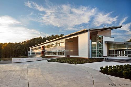
Smithsonian Environmental Research Center - Charles McC. Mathais Laboratory
Edgewater, Maryland
Woods Peacock Engineering Consultants, Inc.
New Construction $25M-$75M - Outstanding Project Award
The Smithsonian Environmental Research Center (SERC) houses the Charles McC. Mathias Laboratory on its 2650 acre campus on the Chesapeake Bay. This project included a 69,000 SF addition to an existing building complex and 23,000 SF of renovations within the original building. The Smithsonian’s goal was to replace temporary trailer spaces and consolidate aging office and lab spaces, while leaving a lighter environmental footprint. Throughout all stages of design, the project team designed for both LEED elements and code-required loads. The original target for the project was LEED Gold. However, the project exceeded that target and was the first Smithsonian building to achieve LEED Platinum. As part of the LEED program, the team designed roofs to support both solar hot water and photovoltaic panels, providing 16% of the on-site electric needs. Another element contributing to the LEED program were foundations specially designed for large cisterns to act as rain barrels for roof runoff which are a component of the buildings 100% water reclamation system. One 10,000 gallon and two 1,400 gallon cisterns are situated on large foundations adjacent to the building. An energy efficient facade wraps the building including insulated wall panels and cantilever light shelves and roof elements for shading. The Central Utility Plant, located in the basement of the addition, houses equipment for geothermal wells. The third floor mechanical room houses the air handling units exterior fume exhaust fans for the laboratory spaces. The project team also incorporated into the design progressive collapse requirements set by the Interagency Security Council (ISC) and the strict floor vibration criteria from the lab equipment manufactures to accommodate the 440x bench microscopes. Other structural challenges included two interior architectural water features, on-site fat clays, bracing of tall flue stacks, fall protection elements, existing underground utilities, and the provision for a future partial second floor addition to allow for additional laboratory space. The design systems and schedule allowed for phased construction to permit continual user operations.
From the Judges: The committee was impressed by the engineer’s involvement in all aspects of the project’s construction, from devising an aluminum scaffolding support-bridge to developing a methodology for attaching the new steel to the original plaster castings. The committee also appreciated the engineer’s commitment to load testing and establishing appropriate factors-of-safety due to the lack of existing codification of allowable properties.
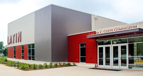
Washington Latin Public Charter School Gymnasium
Washington, DC
Arup
Specialized - Merit Award
Washington Latin Public Charter School Gymnasium is the first cross- laminated timber (CLT) building in Washington,DC. CLT is an innovative engineered wood product gaining wider adoption within the US construction industry, at a speed outpacing acceptance by many building codes. Arup provided structural engineering services for the design of the gymnasium superstructure, developing a code-complaint full timber solution utilizing CLT. To successfully receive permitting approval, Arup leveraged extensive international experience in CLT design and multidisciplinary coordination between code consulting and structural engineering services Arup demonstrated code compliance of the CLT product testing data and developed design solutions utilizing certified fasteners approved by the local authority. The gymnasium superstructure is entirely timber construction, consisting of CLT roof and wall panels and glue-laminated columns & beams. Under gravity loading, CLT roof panels span to glue-laminated girders, which in turn span over 70 ft to glue-laminated columns. Arup achieved a clean structural solution by designing glue-laminated and CLT elements to serve separate functions, with CLT wall panels resisting full lateral loading and glue-laminated members serving as the primary gravity system. The flexural stiffness and rigidity of the CLT allowed for thin panel profiles over long spans compared to equivalent thickness for conventional structural systems and reduced overall structural weight. Arup coordinated with the design team to develop concealed structural connections in order to achieve aesthetic objectives for the fully exposed structure. By using prefabricated connections at typical conditions. Arup reduced construction costs and facilitated case of construction. Addressing the lack of testing data on the use of prefabricated connections with CLT, Arup worked directly with a structural connector manufacturer to test connection configurations. The BIM model developed by Arup ultimately informed the complex openings through CLT panels fabricated by the supplier using Computerized Numerical Control (CNC) machinery. The coordinated approach resulted in a rapid construction schedule, with all CLT panels installed within 3 weeks.
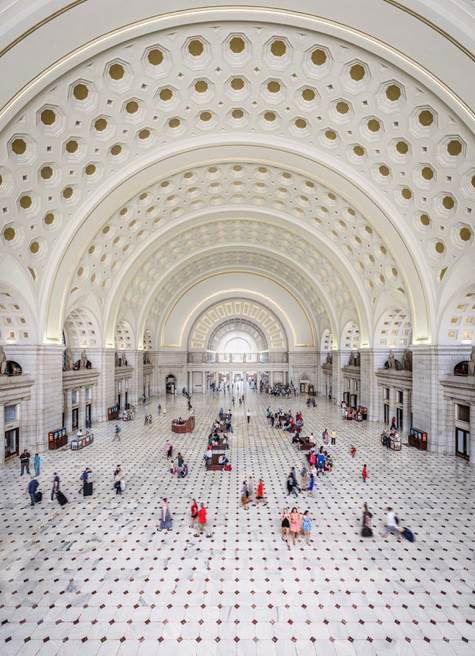
Washington Union Station Historic Main Hall Plaster Ceiling Seismic Retrofit
Washington, DC
McMullan & Associates, Inc.
Renovation $15M-$40M - Outstanding Project Award
After the August 2011 earthquake, McMullan & Associates, Inc. provided an inspection of the vaulted ceiling of the Main Hall in Historic Union Station. In response to inspection findings, McMullan then developed a restoration scheme that provided support of the plaster panels for gravity and seismic loads while maintaining the historic fabric and appearance of the ceiling. The ceiling is composed of 275 cast plaster coffers. The edges of each casting are plastered together to form a continuous barrel between the north and south ends of the Hall. The castings were hung from small wood pieces and steel channels fastened to existing 8” I-beam main runners with a mixture of gypsum plaster and thin wood shavings called excelsior. McMullan was tasked to develop a new method of supporting the existing plaster that also complied with modern seismic code requirements. McMullan worked with scaffolding experts Universal Building Systems to devise an aluminum scaffolding support-bridge which would allow access but keep the Main Hall open to the public. McMullan’s next challenge was to devise a methodology of attaching the new steel framing to the original plaster castings with minimal intervention to the historic fabric. A two pronged solution was developed in conjunction with Historic Preservation Architect John Bowie and Ornamental Plasterer Hayles and Howe. First, after inserting a bolt through the front side of the plaster egg and dart casting, wires were placed through a small hole in the bolt on the backside and wired directly to new light gauge steel supports. Second, wadding composed of gypsum plaster, fiberglass fibers, and burlap was placed directly between new supporting steel framing and the backside of the castings after applying a bonding agent to the existing plaster. Since there is no published load data for a plaster hanging system and no guidance is provided in the IBC, McMullan devised a series of load tests to determine safe loading capacities. Pieces of original plaster ceilings from the ceiling area attached to new light gauge steel by plaster wadding.
From the Judges: The committee was impressed by the engineer’s involvement in all aspects of the project’s construction, from devising an aluminum scaffolding support-bridge to developing a methodology for attaching the new steel to the original plaster castings. The committee also appreciated the engineer’s commitment to load testing and establishing appropriate factors-of-safety due to the lack of existing codification of allowable properties.
Bunny Mellon Healing Garden Dedicated to the First Ladies of the United States
Children’s National Medical Center, Washington, DC
Simpson Gumpertz & Heger
Renovation Under $15M - Outstanding Project Award
At the Children’s National Health System’s Main Campus, in a congested area of Washington, DC, administrators try to maximize their available space. The hospital wanted to build a garden to give some respite to patients and their families and initially engaged the firm to evaluate the feasibility of building a roof garden. The design team determined that the existing framing could be strengthened to support the new rooftop loads. The Healing Garden located on the 3rd level of the original 1970’s building is expected to open later this year. Surrounded on three sides by taller wings of the glass-enclosed hospital, the garden is open to a view of the city on the 4th side. The project presented interesting challenges. For scheduling reasons, the hospital wanted to secure a permit and begin structural strengthening work before the final rooftop landscape design would be completed. To design a strengthening scheme without defined loads, the project team worked to establish loading parameters in line with the hospital’s vision and developed an overburden loading diagram for the structural permit drawings. The diagram shows locations of trees; defines regions of heavy, medium, and light loading; and lists maximum allowable superimposed dead loads for each region, ranging from 40 psf to 430 psf. Approaching load development and permitting in this unconventional way allowed the team to create an efficient strengthening design affording the architect sufficient flexibility to complete their own design while the contractor began structural work. Another set of challenges related to the original construction below the Healing Garden. The hospital provided original building drawings showing framing layout and sizes, but lacked shop drawings showing connection details. The team accessed the interstitial space, navigated the maze of ducts and pipes, observed framing through exploratory openings in finishes, and documented typical roof and truss framing and connection details.
From the Judges: The committee was impressed by the team’s collaborative approach to issuing permitting documents before final design loads from the garden were determined. In addition, the commitment of the design team to locate, document, understand, and safely alter the existing conditions and connections were critical to the success of this project.
RagingWire VA2 Data Center
Ashburn, Virginia
Rathgeber/Goss Associates
Renovation Over $40M - Merit Award
RagingWire acquired this project’s two story structure for their VA2 Data Center. Built in 2011, the 123,000 SF existing structure consisted of load-bearing exterior concrete wall panels, with a two story interior steel frame. The 2nd floor and roof framing consist of steel joist girders framing to wide flange columns and supporting open web steel joists. At the 2nd floor, a concrete slab on form deck is carried by joists spaced at 2ft on center. Reinforced concrete spread footings supported existing columns which penetrated the roof surface with the capacity to carry up to 120 kips of additional load. Lateral forces are resisted by the precast concrete shear walls. Rathgeber/Goss Associates worked with the design team and contractor on a fast track, design build approach. With limited exterior openings, the building was ideal for conversion to a data center. With the available vertical column expansion capabilities, along with a roof designed for only a 30 psf live load, the design team elected to build an additional penthouse floor at 3 1/2 to 4ft above the existing floors using air-side economization by allowing air into a cooling plenum on one side of the building, which then flows under a raised floor and into the equipment area. Exhaust heat exits through louvers on the other side of the hall. The plenum was created by removing a 4’-0” wide section of roof deck between the existing roof joists. A new penthouse roof was constructed using steel beams, open web joists, and galvanized roof deck. To maintain the entirety of the existing 2 floors as seven 12,500 SF data halls and equipment rooms, a 40ft wide 2nd floor expansion of 15,000 SF was added full length along the building’s south face to be used as offices and operations centers. These rooms were designed to allow flexibility for subdividing and customizing among tenants. New steel columns above grade were held 16 ft inboard from the new face of the building with cantilevered girders supporting the 2nd floor joists and a transfer column at the cantilever end. The long cantilever allowed for 34 covered parking spaces under the addition to serve the small building population.
From the Judges: The committee appreciated this project’s fast-track design-build approach to meet the client’s schedule. The new penthouse over the existing roof, along with the plenum space created by removal of the existing deck, provided creative solutions to engineer a building capable of meeting the high-end demands of a data center.
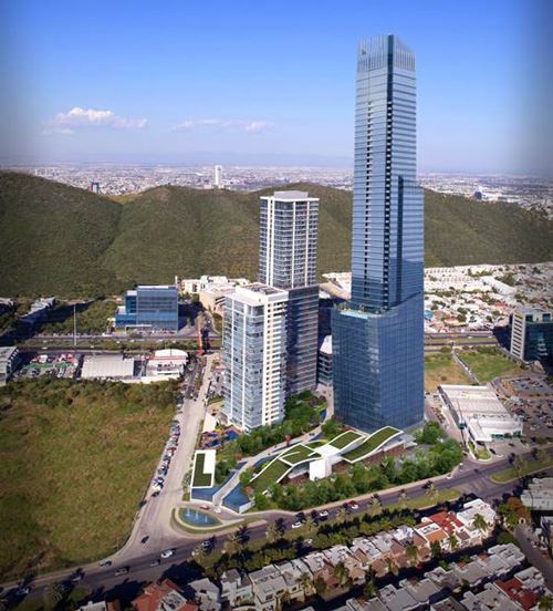
Thornton Tomasetti Group, Inc.
New Construction Over $75M - Merit Award
At 279 meters, the 69 story Torre Koi will become the tallest building in Mexico, and the third tallest in Latin America, when it is completed in 2017. The mixed-use tower consists of 9 levels of below-grade parking; a ground floor lobby, 20 levels of office space; 36 levels of residential space, with 218 apartments and 18 penthouses; 2 mechanical floors; and an amenities level with a swimming pool on the 22nd floor. Thornton Tomasetti and local partner Stark & Ortiz were brought into the project after wind-tunnel testing identified excessive lateral displacements and acceleration in the structure - after the architectural design was substantially complete and 30% of the residential units were sold. The firm designed the structural system to fit to the building’s pre-established form with a minimum architectural impact. The new design addressed vertical gravity loads, large horizontal wind and seismic forces, serviceability concerns of lateral wind and seismic load deflection, horizontal building acceleration due to wind and the differential vertical-shortening of columns and walls caused by time-dependent creep and shrinkage. The tower’s slenderness (with a height to width ratio of 8.7:1) and building core slenderness (19.15:1) required a lateral-force-resisting system that coupled the central core with perimeter columns. The project team developed a “virtual outrigger” system that used stiff diaphragm slabs and reinforced concrete belt walls at the perimeters of the mechanical spaces at the 21st and 62nd floors. These elements work together as indirect outriggers to transfer part of the overturning moment from the core to the perimeter columns; the stiff floor diaphragms cause the belt walls to tilt and follow the core’s rotation. The virtual outriggers efficiently increase structural stiffness without significantly affecting architectural or mechanical layouts. Additional stiffness was still required, however, leading the team to replace the originally planned one-way beam and slab tower floor systems with heavier post-tensioned flat-slab floor framing. This added mass further reduces wind accelerations.
From the Judges: The committee appreciated the design team’s commitment to preserving the architectural design while finding creative engineering solutions to the wind-tunnel-identified lateral displacements and accelerations, including the “virtual outrigger” system.
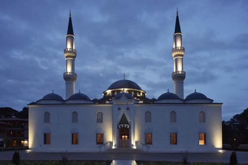
The Turkish American Community Center
Lanham, Maryland
The SK&A Group
New Construction Over $75M - Outstanding Project Award
The Turkish American Community Center (TACC) is a large, mixed-use project located in . The Turkish government funded the project as a religious and cultural center for Turkish Americans and others to enjoy. A large, single story concrete parking garage structure connects five other structures: the Mosque, the Turkish Bath building, the Fellowship Hall, the Cultural Center, and the Guesthouse/Convent Monastery. One of the unique challenges of this project was that the buildings varied in required height, open floor spans, etc., and so various structural systems including conventionally-reinforced concrete, post-tensioned long-span beams, steel framing and light gage trusses were employed to create cost-effective designs. The project soils report identified large amount of expansive clays, so foundation reinforcing detailing was critical to all locations. The Fellowship Hall is a one story structure intended to house a coffee shop and cafeteria. The Guesthouse/Convent Monastery, where visitors can rent a room for the night, was designed utilizing a steel beam and column approach. The Cultural Center has a more irregular layout and required a large cantilever over the theatre projection space and a long-span, open space at the library. The Turkish Bath building houses traditional Turkish baths, a swimming pool, and large basketball court. The most significant achievement of the project was the Mosque. The structure is entirely cast-in-place, conventionally reinforced concrete. Certain dimensions of the Mosque needed to be maintained for their religious significance and designed without adjusting the overall concrete geometry. Four concrete arches support the center dome and tie into concrete columns in the corners. SK&A designed these columns to be hollow in order to accommodate mechanical needs. Both a design architect from Turkey (HASSA) and a local architect from Washington, DC (Fentress Architects) developed the plans, adding further challenges. The design architect produced basic-level plans and elevations which SK&A and Fentress used to produce structural and architectural drawings. Based on the pace of the project, some of the structural detailing needed to be done concurrently with or prior to the completion of architectural drawing production. Careful coordination between SK&A and Fentress was paramount in fulfilling the design intent while also satisfying the local building codes.
From the Judges: The committee was impressed by the team’s collaborative approach to issuing permitting documents before final design loads from the garden were determined. In addition, the commitment of the design team to locate, document, understand, and safely alter the existing conditions and connections were critical to the success of this project.
Ellsworth Place Mall
Silver Spring, Maryland
Ehlert Bryan
Renovation Under $15M - Merit Award
In 1992, an existing, six story, 1940’s era concrete framed retail building was expanded into a five story urban mall. The expansion added 385,000 SF of structural steel framing to the existing building to provide space for a 5th floor theater, 70 retailers and capacity to allow an addition seven story vertical office tower expansion. Twenty years later, the building required further renovation. The renovation and modernization consisted of revising vertical circulation through the mall, infilling the sloped floors of the movie theater, adding multiple exterior sign boards, and upgrading the capacity of the building to support a future nine story vertical tower expansion. The tower expansion was 31% larger in floor area and 42% taller than the original tower assumed in the 1990’s. Results of a 3D analysis model indicated that more than half of the original braced frame members, 15% of the gravity columns and several of the foundations elements were overstressed. Under the footprint of the future tower, several existing columns stopped at the 5th floor, further complicating the framing. As design progressed, assumptions for the future tower framing were refined by locating the 1st floor of the tower 8ft above the highpoint of the roof, allowing the use of transfer girders to span over the 60ft bays and creating a stiff lateral load transfer mechanism between the future moment frames and the original braced frame systems. This technique decreased the moments transferred to the lower columns to acceptable levels. Column sizes of the office tower moment frame were up-sized to reduce overall building slenderness, decreasing wind gust factors, and therefore the wind loads. Several column footings for the lower level braced frames were found to have insufficient capacity for the uplift load combinations. Uplift resistance capacity was increased by adding rock anchors and engaging the underlying bedrock. The major additions to the floor plans included 4 freight elevators between specific floors and 14 new escalators with numerous adjustments to slab openings. Hand analysis combined with the 3D analysis model yielded solutions that required beam and connection strengthening, along with some new columns. Composite design was used whenever possible.